
- Are you a Final year student????
Confusions with your projects????
Worries about your Campus Recruitment????
Want Best Institute to solve all your technical problems?????
Contact:
FemtoSoft Computer Education. We Provide Free Project & Career Oriented counseling)

The following article will guide you how to do your college project very easily

What is an abstract?
An abstract is a concise summary of a
completed research project or paper. A
well-written abstract will make the reader want to learn more about your
research, read your paper, or attend your presentation. Abstracts also serve as a summary of the
research so the paper can be categorized and searched by subject and keywords.
How long is an abstract?
Generally, abstracts are limited to
200 to 300 words, but the exact word limit will be stated by the publication,
conference, or organization requesting the abstract.
Components of an abstract
- · Motivation or Statement of Problem:
Why do we care about the problem?
What practical, theoretical, scientific, or artistic gap is your research
filling?
- · Methods or Approach:
What did you actually do to get
your results? Did you analyze three
plays, interview 125 students, write a memoir, invent a more powerful
photovoltaic cell, or translate a book? Did you approach your subject using a
specific theoretical framework, technical procedure, or methodology?
- · Results or Product:
As a result of completing the above procedure
or investigation, what did you learn, create, or invent?
- · Conclusions or Implications:
What are the larger implications of your findings, especially for the
problem or gap identified in Step 1?
Tips for writing an abstract
- It takes lots of revision to write a good abstract! Expect to spend some time preparing your abstract before submitting it.
- Find the main point of your paper or research and phrase it in a way that can be understood by an educated non-expert.
- You may repeat sentences from your paper in your abstract. In some cases, your paper’s introductory paragraphs may be suitable for the abstract, but they will have to be condensed and rewritten to fit the purposes of the abstract.
- Remember to use keywords important to your field of research or to use words that indicate your field (biochemical engineering, for example, or the history of Byzantine art).
- Your abstract should not be so detailed that it requires quotations, citations, or footnotes. Remember, it’s a summary!
- If you are finding it difficult to summarize your paper or research concisely, write several paragraphs initially then cut and condense it to one paragraph.
- If you are finding it difficult to meet the word limit, seek the help of an outsider reader (a friend or writing tutor) to help you cut excess words.
Data flow diagram

A data flow diagram (DFD) is a graphical representation of the "flow" of data
through an information system, modeling
its process aspects. Often they are a preliminary
step used to create an overview of the system which can later be elaborated.
DFDs can also be used for the visualization of data processing (structured design).
A DFD shows what kinds
of information will be input to and output from the system, where the data will
come from and go to, and where the data will be stored. It does not show
information about the timing of processes, or information about whether
processes will operate in sequence or in parallel (which is shown on a flowchart).
Data Flow Diagrams Symbols
- There are some symbols that are used in the drawing of business process diagrams (data flow diagrams).
- These are now explained, together with the rules that apply to them.
- Flow diagrams in general are usually designed using simple symbols such as a rectangle, an oval or a circle depicting a processes, data stored or an external entity, and arrows are generally used to depict the data flow from one step to another.
1. External entities (source/destination
of data) are represented by squares
2. Processes (input-processing-output) are represented by
rectangles with rounded corners;
3. Data Flows (physical or electronic data) are represented by
arrows; and finally,
4. Data Stores (physical or electronic like XML files) are
represented by open-ended rectangles.
These four components can be represented by four simple symbols. These symbols can be explained in detail as follows:
Basic Symbols
Ø
A double square for an external entity
Ø
An arrow for movement of data from one point to another
Ø
A rectangle with rounded corners for the occurrence of a
transforming process
Ø An open-ended rectangle
for a data store
Symbols used in DFD:

An example for DFD diagrams

FRONT END & BACK
END
A
"front-end" application is one
that application users interact with directly. A "back-end"
application or program serves indirectly in support of the front-end services,
usually by being closer to the required resource or having the capability to
communicate with the required resource.
The
back-end application may interact directly with the front-end or, perhaps more
typically, is a program called from an intermediate program that mediates
front-end and back-end activities.
ENTITY RELATIONSHIP
An
entity-relationship diagram is a data modeling technique that creates a graphical
representation of the entities, and the relationships between entities, within
an information system.
The three
main components of an ERD are:
·
The entity is a person, object,
place or event for which data is collected. For example, if you consider the
information system for a business, entities would include not only customers,
but the customer's address, and orders as well. The entity is represented by a
rectangle and labeled with a singular noun.
·
The relationship is
the interaction between the entities. In the example above, the customer places an order, so the word
"places" defines the relationship between that instance of a customer
and the order or orders that they place. A relationship may be represented by a
diamond shape, or more simply, by the line connecting the entities. In either
case, verbs are used to label the relationships.
·
The cardinality defines the
relationship between the entities in terms of numbers. An entity may be optional: for example, a sales rep
could have no customers or could have one or many customers; or mandatory: for example, there must be
at least one product listed in an order. There are several different types of cardinal notation; crow's foot
notation, used here, is a common one. In crow's foot notation, a single
bar indicates one, a double bar
indicates one and only one (for
example, a single instance of a product can only be stored in one warehouse),
a circle indicates
zero, and a crow's foot indicates
many. The three main cardinal relationships are: one-to-one, expressed as 1:1;
one-to-many, expressed as 1:M; and many-to-many, expressed as M:N.
The steps
involved in creating an ERD are:
·
Identify the entities.
·
Determine all significant interactions.
·
Analyze the nature of the interactions.
·
Draw the ERD.
EXAMPLE DIAGRAMS
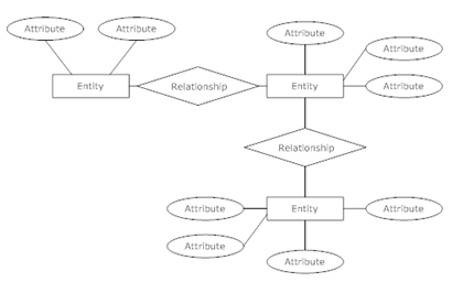
ELEMENTS IN ER DIAGRAMS

There are three basic elements in an ER Diagram: entity,
attribute, relationship. There are more elements which are based on the main
elements. They are weak entity, multivalued attribute, derived attribute,
weak relationship and recursive relationship. Cardinality and ordinality
are two other notations used in ER diagrams to further
define relationships.
Entity
An entity can be a person, place, event, or object that is
relevant to a given system. For example, a school system may include students,
teachers, major courses, subjects, fees, and other items. Entities are
represented in ER diagrams by a rectangle and named using singular nouns.
Weak Entity
A weak entity is an entity that depends on the existence
of another entity. In more technical terms it can defined as an entity that
cannot be identified by its own attributes. It uses a foreign key combined with
its attributed to form the primary key. An entity like order item is a good
example for this. The order item will be meaningless without an order so it
depends on the existence of order.
Attributes
An attribute is a property, trait, or
characteristic of an entity, relationship, or another attribute. For example,
the attribute Inventory Item Name is an attribute of the entity Inventory Item.
An entity can have as many attributes as necessary. Meanwhile, attributes can
also have their own specific attributes. For example, the attribute “customer
address” can have the attributes number, street, city, and state. These are called
composite attributes. Note that some top level ER diagrams do not show
attributes for the sake of simplicity. In those that do, however, attributes
are represented by oval shapes.

Multi valued attribute
If an attribute can have more than
one value it is called an multi valued attribute. It is important to note that
this is different to an attribute having its own attributes. For example a
teacher entity can have multiple subject values.

Derived attribute
 An attribute based on another
attribute. This is found rarely in ER diagrams. For example for a circle the
area can be derived from the radius.
An attribute based on another
attribute. This is found rarely in ER diagrams. For example for a circle the
area can be derived from the radius.
Relationship
A relationship describes how entities
interact. For example, the entity “carpenter” may be related to the entity
“table” by the relationship “builds” or “makes”. Relationships are represented
by diamond shapes and are labeled using verbs.